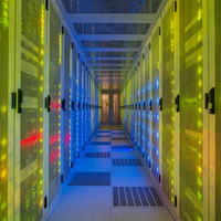
In liquid-cooled data centers, there are data points, sights and sounds all around that serve as flashing warning signs of impending challenges.
A slow drip. A pressure reading that drifts a few PSI lower than expected. A pH value that has quietly crept below 7.5.
In a liquid-cooled data center, these can be early signals of a failure chain that, left unaddressed, can take down hardware, crater uptime, and land an operations team in a very uncomfortable conversation with the C-suite. If you're a person in charge of a transition to direct liquid cooling (e.g., direct-to-chip cooling), you need to, in simple terms, pay close attention to these signs.
Even a few moments of inattention can end up costing you exponentially many more moments spent fixing a big problem, like a leak, not to mention the cost of unplanned downtime.
It's, literally and figuratively, drip, drip drip ... until it's not. Then you have a much bigger problem.
Direct-to-chip and other liquid cooling architectures are quickly growing to become the default thermal management strategy for high-density AI and HPC deployments. As such, the importance of proactive coolant monitoring has grown in direct proportion to rack power densities.
As coolants needs get bigger and bigger, the person who keeps watch of these systems and springs into action will serve a critical function.
Why Coolant Leaks Are So Consequential in Liquid-Cooled Data Centers
Air-cooled racks and liquid-cooled racks fail differently.
In an air-cooled row, a fan failure raises temperatures; a management system flags the condition; operators respond. The hardware is, for the most part, sealed off from the thermal medium.
Liquid cooling inverts this dynamic. While liquid cooling systems bring the additional heat transfer capacity needed for HPC environments in a way that air cooling alone cannot, the consequences of a liquid cooling failure can be sudden and hard to miss.
The coolant — propylene glycol solution, dielectric fluid, or water — is routed in close physical proximity to processors, cold plates, manifolds, and quick-connect fittings. When something leaks, the hardware and the hazard occupy the same space.
The consequences are correspondingly severe. Liquid exposure can cause immediate short-circuit events, corrosive damage to printed circuit board (PCB) traces, or gradual oxidation that degrades component reliability over months before a failure is visible (Envigilance, 2026).
Because these events are often unplanned and rapid, the financial impact tends to be disproportionate. Not only that, downtime costs have been on the rise.
Industry data from 2022 notes 60% of outages cost more than $100,000, up from 39% in 2019. Furthermore, outages costing more than $1 million increased from 11% to 15% during that same timeframe (Uptime Institute, 2022).
Water and coolant events rank persistently among the top five root causes of unplanned data center outages globally (Uptime Institute, as cited in Envigilance, 2026). That consistency matters: it means this is not a long-tail risk. It is a predictable, recurring failure mode — one that detection and monitoring programs are specifically designed to prevent. 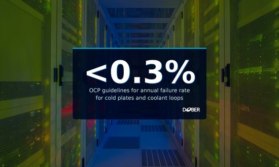
The Open Compute Project's liquid cooling guidelines acknowledge this directly, targeting an annual cold plate and coolant loop failure rate of 0.3% or lower as a design and operational goal (Chen et al., 2023). For a large fleet with thousands of cold plates in circulation, even that low failure rate demands a serious detection and response infrastructure.
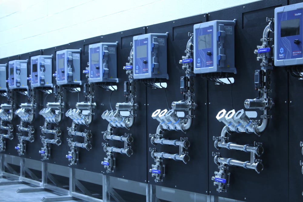
Solutions like Dober's Glycol Closed Loop Monitoring Panel can help data center operators keep tabs on all of the relevant indicators to better predict potential leak conditions and more quickly respond when they occur.
The Detection Gap
One of the most actionable findings from recent monitoring research is the gap between detection methods. The axiom "time is money" is particularly true when it comes to data center cooling system leak events. Every second counts.
Facilities that rely on visual inspection won't be able to respond to incidents with the same speed as those with integrated leak detection systems.
The physics of liquid-cooled hardware means that gap is not incidental: it often determines whether an incident is a service call or a hardware replacement event.
Coolant Chemistry Degradation: What to Test, and Why It Matters
A common misconception about propylene glycol-based coolants is that once they are filled, commissioned, and confirmed at the right concentration, they can be left alone. In practice, the chemistry of a closed cooling loop is not static. It evolves — and the direction it tends to evolve, without active management, is toward conditions that accelerate corrosion and reduce thermal performance.
How Glycol Degrades
Propylene glycol oxidizes in the presence of oxygen, heat, and metallic catalysts — conditions that are, unfortunately, built into the operating environment of a coolant distribution unit (CDU) and cold plate loop. The oxidation products are organic acids, primarily glycolic, lactic, and formic acids. As these accumulate, they consume the fluid's alkalinity reserve and depress pH (R2J Engineering, 2025). When system pH falls below 7.0, ferrous metals begin to rust and nonferrous metals — the copper, brass, and aluminum that make up cold plates, manifolds, and brazed joints — begin to corrode aggressively (Rheonics, n.d.).
Corrosion inhibitors are added specifically to buffer this degradation, passivate metal surfaces, and keep the loop chemistry stable. But inhibitors are consumable. They deplete as they do their job, and a loop that was properly inhibited at commissioning may be significantly under-protected at a later date without anyone noticing.
A peer-reviewed comparative analysis of single-phase data center coolants, conducted under ASTM D1384 and ASTM D8040 test standards, found that properly inhibited propylene glycol-based fluids maintained corrosion rates well within specification limits for copper, brass, solder, and aluminum — but that performance is contingent on maintaining adequate inhibitor concentrations (Zimmermann et al., 2025). Once inhibitors are depleted, corrosion rates on aluminum and copper rise sharply.
Key Parameters to Monitor
ASHRAE TC 9.9 and the OCP's Guidelines for Using Propylene Glycol-Based Heat Transfer Fluids in Single-Phase Cold Plate-Based Liquid Cooled Racks both specify that operators should actively monitor coolant quality as part of ongoing system maintenance (ASHRAE TC 9.9, 2024; Open Compute Project, 2022). The key parameters are:
pH. In its guidelines for PG 25 and PG 55 heat transfer fluids, OCP specifies a fluid target pH of 8.0–10.5 for propylene glycol-based secondary loops, with the caveat that "fluid pH is dependent on corrosion inhibitor formulation and may be lower when using organic acid technology (OAT)" (Open Compute Project, 2022). Values outside this range signal either acid accumulation (low pH) or inhibitor over-treatment that can cause scaling (high pH). Testing with a calibrated meter, not pH strips, is recommended for accuracy.
Reserve alkalinity. This measures the buffering capacity remaining in the fluid — essentially, how much more acid the inhibitor package can neutralize before pH begins to fall. Declining reserve alkalinity is an early warning that inhibitors are being consumed faster than expected, often due to oxygen ingress, elevated temperatures, or galvanic activity from dissimilar metals in the loop.
Glycol concentration. Measured by refractometer, glycol concentration should be verified at commissioning and at regular service intervals. Concentration can shift due to evaporation, top-off with improperly diluted fluid, or minor leak-and-replenishment cycles. For PG 25 loops, the target is approximately 25% propylene glycol by volume — enough to provide freeze protection to roughly -10°C while keeping viscosity and pumping losses close to water performance (ASHRAE TC 9.9, 2020).
Visual clarity. Cloudy or discolored fluid can indicate particulate contamination, microbial growth, or corrosion byproduct accumulation. Inline optical sensors and periodic physical samples both serve this function.
Conductivity. For facilities operating ultra-low conductivity (ULC) loops — common in fuel cell cooling and some immersion-adjacent architectures — conductivity monitoring is a primary quality metric. For standard PG 25 loops, it is a supplementary indicator.
Rheonics and other inline sensor manufacturers have documented the use of real-time viscosity and density monitoring as a proxy for glycol degradation, noting that oxidized glycol exhibits measurable viscosity changes before pH drops to critical levels — offering an earlier warning window than chemistry testing alone (Rheonics, n.d.).

Recommended Testing Frequency
Neither ASHRAE nor OCP prescribes a universal testing interval, as frequency depends on loop size, makeup water quality, operating temperature, and metallurgy. In practice, most operators in mission-critical environments perform a baseline chemistry panel at commissioning, a full panel at three and six months, and then annually — with pH spot-checks quarterly in between. Facilities with known oxygen ingress issues, recent leaks, or mixed metallurgy in the loop should test more frequently.
Dober's FluidIQ™ monitoring program provides comprehensive fluid testing and analysis programs that maximize service life and ensure long-term system reliability.
What ASHRAE and OCP Specify for Monitoring and Leak Detection
There's a lot of information out there, but sometimes it can be difficult to know where to focus your attention. Knowing what the standards bodies say helps provide a defensible basis for the monitoring investments operators make. In other words, it help you build a clear framework for what "adequate" looks like when an incident review happens.
ASHRAE TC 9.9
ASHRAE Technical Committee 9.9 (Mission Critical Facilities, Data Centers, Technology Spaces, and Electronic Equipment) is the primary technical authority for data center thermal management guidance in North America and, increasingly, globally. Its publications are not mandatory codes in most jurisdictions, but they function as the de facto standard of care for mission-critical design and operations.
The TC 9.9 Liquid Cooling Guidelines for Datacom Equipment Centers (Datacom Series Book 4) identifies coolant quality monitoring and filtration as operational requirements, noting that deteriorating fluid chemistry leads directly to lower efficiency and increased energy consumption — not just corrosion (ASHRAE TC 9.9, 2020). The Thermal Guidelines for Data Processing Environments, 5th Edition (2021), establishes facility water classes (W17 through W+) for liquid-cooled systems, each with defined temperature and quality parameters that secondary loops must maintain (ASHRAE TC 9.9, 2021).
Notably, TC 9.9 published 2024 Liquid Cooling: Resiliency Guidance for Cold Plate Deployments specifically to address the operational challenges that arise as direct-to-chip becomes mainstream — including leak response, CDU redundancy, and coolant quality management during hardware refresh cycles (ASHRAE TC 9.9, 2024). The document reflects the industry's recognition that the thermal management challenges of AI-scale GPU deployments are pushing coolant management into "uncharted territory" (Data Center Dynamics, 2024).
ASHRAE's structural recommendation is to deploy a Coolant Distribution Unit (CDU) to create a defined demarcation between the Facility Water System (FWS) and the Technology Cooling System (TCS). The CDU serves as both a thermal interface and a containment boundary — if the TCS loop has a chemistry problem or a leak event, it does not propagate directly into the building's chilled water or cooling tower infrastructure (ASHRAE TC 9.9, 2020).
Open Compute Project (OCP)
The OCP's Guidelines for Using Propylene Glycol-Based Heat Transfer Fluids in Single-Phase Cold Plate-Based Liquid Cooled Racks is the most operationally specific document in this space. It covers wetted-material compatibility requirements, manifold and tubing specifications, operating temperature and pressure ranges, filtration standards, and safety practices — with the goal of enabling interoperability across IT vendors and refresh cycles (Open Compute Project, 2022).
On leak detection specifically, OCP's OAI System Liquid Cooling Guidelines calls for leak detection integration at the rack and CDU level, recommending that operators design for immediate automated alerts rather than relying on periodic inspection (Chen et al., 2023). The OCP's ACF Reference Design Guidance further codifies leak detection as a component of the rack cooling architecture, not an afterthought (Open Compute Project Cooling Environments WG, n.d.).
Together, these documents establish that ASHRAE and OCP have reached broad convergence: coolant quality monitoring and automated leak detection are not optional enhancements. In an effective direct liquid cooling program, these are baseline operational requirements.
Leak Detection Technologies: From Sensor Cables to Smart Systems
The toolset for coolant leak detection has matured significantly as liquid cooling adoption has accelerated. Operators today have options ranging from passive indicator tapes and point sensors to fully networked, AI-assisted forecasting systems. The right approach depends on facility size, risk tolerance, and integration with existing building management infrastructure.
Point Sensors and Leak Detection Cables
The most widely deployed technology is resistive leak detection cable — a continuous sensing element routed under raised floors, along pipe runs, and beneath CDUs. When the cable contacts liquid, resistance changes and triggers an alarm, typically with zone-level localization to help maintenance teams respond quickly.
Point sensors serve a similar function at specific high-risk locations: beneath quick-connect manifolds, at CDU drain ports, and under coolant header pipes.
These passive systems are reliable, cost-effective, and integrate easily with standard building management systems (BMS) via dry contact or analog outputs. Their limitation is that they detect leaks after fluid has reached the floor or cable — they do not provide early warning before a fitting fails. In other words, they're good things to have, but probably shouldn't be your only tool in leak defense and response.
Flow and Pressure Monitoring
A more proactive detection layer uses flow meters and differential pressure sensors within the coolant loop itself. A sustained drop in loop pressure, a flow imbalance between supply and return, or an unexpected change in CDU pump speed can all signal a developing leak before visible fluid appears.
Many modern CDUs include these sensors natively; integrating their output into BMS dashboards and setting alert thresholds is a configuration task, not a capital investment. Flow-based monitoring is particularly valuable for detecting slow leaks at manifold connections and cold plate quick-disconnects — the failure points that resistive cables may not catch until significant fluid has already escaped.
Smart IoT-Based Monitoring and Predictive Detection
The leading edge of leak detection combines real-time sensor data with machine learning models to move from detection to forecasting — identifying conditions likely to produce a leak before the leak occurs.
A 2024 research paper demonstrated a system combining Long Short-Term Memory (LSTM) neural networks for probabilistic leak forecasting with Random Forest classifiers for real-time detection (Sunkara & Konakanchi, 2024). Tested against synthetic data aligned with ASHRAE 2021 standards, the system achieved 96.5% F1-score and 87% forecasting accuracy within a 30-minute tolerance window. For a representative 47-rack facility, the authors estimated that proactive maintenance enabled by this approach could prevent approximately 1,500 kWh of annual energy waste from unplanned shutdowns and extended repair periods. It should be noted, however, that the paper is a preprint and not yet through formal peer review, and uses synthetic data calibrated to ASHRAE 2021 parameters, with the authors noting results represent upper bounds pending empirical validation.
The practical value of smart monitoring systems is the response-time compression they enable. Research cited earlier in this article noted that facilities using integrated detection systems respond to cooling incidents in 8–12 minutes on average, versus 2–4 hours for facilities dependent on visual inspection (Envigilance, 2026). In a liquid-cooled environment, that difference in response time is frequently the difference between a minor service event and a hardware loss incident.
Integration Considerations
Regardless of which detection technology an operator deploys, the critical integration point is the BMS or data center infrastructure management (DCIM) platform. Detection that generates an alarm on a standalone panel in a mechanical room does not help the NOC respond. Alarm routing, escalation thresholds, and defined incident response protocols — specifying who is notified, what the first action is, and when hardware shutdown is triggered — transform a detection investment into an operational capability.
As the old saying goes, if a tree falls in the forest and no one is around to hear it, does it make a sound? In data centers, you can't afford to have those alarms go unheard or unnoticed because they are isolated to certain stations/physical locations.
OCP guidance specifically recommends designing for automated alert propagation rather than manual inspection cycles, and ASHRAE's resiliency guidance emphasizes the importance of maintaining thermal inertia and active redundancy so that cooling systems can sustain operations during the response interval after a leak is detected (ASHRAE TC 9.9, 2024; Chen et al., 2023).
The Energy Efficiency Connection: Coolant Monitoring as a PUE Strategy
The operational case for coolant monitoring is usually framed around risk reduction — preventing leaks from becoming outages. That framing is correct, but it's only part of the picture.
The condition of the coolant itself, independent of leak events, has a direct and measurable effect on data center energy efficiency.
How Degraded Coolant Hurts PUE
Propylene glycol's viscosity and specific heat capacity change as the fluid degrades. Oxidized glycol is more viscous than fresh fluid at the same concentration — meaning the CDU pumps must work harder to maintain the same flow rate, increasing parasitic power consumption. Simultaneously, accumulated corrosion byproducts and particulate contamination can partially foul micro-channel cold plate surfaces, increasing thermal resistance and forcing processors to operate at higher temperatures.
That's when those dreaded two words come into play: Thermal throttling — where CPUs and GPUs reduce clock speeds to manage junction temperature — is an underappreciated efficiency loss in poorly maintained liquid-cooled loops.
The Lawrence Berkeley National Laboratory's Center of Expertise for Energy Efficiency in Data Centers documents how well-maintained liquid cooling systems achieve dramatically better Power Usage Effectiveness (PUE) than conventional air-cooled designs — with purpose-built, optimally operated liquid-cooled facilities reaching PUE values as low as 1.034 (LBNL, n.d.; Van Geet, n.d.). Maintaining those efficiency gains requires the loop to remain in specification. A liquid cooling system that was designed for PUE 1.05 but operates with degraded fluid and partially fouled cold plates may perform closer to PUE 1.15 or 1.20 — a meaningful gap at data center scale.
Quantifying the Energy Impact of Leak Events
Beyond ongoing efficiency loss, undetected leaks impose acute energy costs. The IoT-based monitoring research cited above estimated that a 47-rack facility without proactive leak detection loses approximately 1,500 kWh annually to unplanned shutdowns, extended repair periods, and partial system restarts following cooling incidents (Sunkara & Konakanchi, 2024). At current commercial electricity rates, that is not a trivial line item — and it scales with fleet size.
The DOE's Federal Energy Management Program (FEMP) and WBDG's data center energy efficiency guidance both identify cooling system maintenance — including fluid quality management — as a primary lever for improving data center energy performance, alongside server virtualization and airflow management (WBDG/FEMP, n.d.).
The Compounding Argument
When leak risk reduction, hardware protection, and energy efficiency are considered together, the ROI case for a comprehensive coolant monitoring program becomes straightforward. The investment in pH testing, inline sensors, and detection infrastructure is modest relative to the cost of a single significant cooling incident — and it pays dividends in efficiency every day that it prevents a loop from drifting out of specification.
Learn About Dober's Glycol Monitoring Panels >
Keeping Your Liquid Cooling Loop in Specification
Liquid cooling is no longer an exotic architecture reserved for national laboratories and hyperscalers. It is the standard approach for GPU-dense AI training clusters, high-performance compute environments, and an increasing share of general-purpose enterprise deployments. With that adoption comes the operational responsibility to manage coolant quality and leak risk with the same discipline applied to any other critical system.
So, if you're navigating that transition and are trying to figure out how to get your liquid cooling program going on the right foot, what do you need to do? In summary:
-
Select a properly inhibited, industry-standard fluid
-
Test chemistry at defined intervals
-
Deploy detection infrastructure at leak-prone points
-
Integrate alerts into your BMS or DCIM
-
Maintain a defined incident response protocol
Dober formulates COOLWAVE™ DC-25, a PG 25-class heat-transfer fluid recognized under the OCP Inspired™ program. If you are evaluating coolants for a new or retrofit liquid-cooling deployment — or if you have questions about testing, inhibitor management, or material compatibility — our chemistry team is available to review your specification and recommend a fluid-and-inhibitor system aligned with the standards discussed above.
To learn more about our monitoring services, check out our FluidIQ summary of offerings.
References